SOP — Fermentation Tank CIP
FUERST WIACEK Version 2.0 | Cellar — all fermentation tanks | Frequency: after every tank emptying
Purpose
Clean tanks are essential for consistent, stable fermentation. This SOP covers the full CIP procedure for fermentation tanks after emptying: cone dump, water rinse, sterile air purge, pre-caustic, main caustic, deck scrub, acid, and PAA sanitisation. The process uses the mobile pump and mobile dosing tank.
Note
The Botec recipe CIP Gär- & Lager Tanks [1] V 1.00 exists in 003 → CIP but is not used. All fermentation tank CIPs are performed manually using the mobile pump and dosing tank as described in this SOP.
PPE Required
Warning
Do not handle chemicals without full PPE.
- Safety goggles
- Chemical-resistant gloves
- Ear protection
Risks
| Hazard | Risk |
|---|---|
| Chemical exposure | Burns, eye damage / blinding |
| Running pump dry | Pump damage — never run without liquid in the inlet |
| Tank implosion | Sending caustic to a tank with CO₂ pressure — always fully vent before CIP |
| Asphyxiation | CO₂ displacement during venting — ensure adequate ventilation |
| Compressed air | Can push liquid out at force — control carefully |
| Hose lifting off drain | Hose can fly off when gas breaks through at end of cone dump — use a lid to hold it down |
| Working at height | Use appropriate access equipment on deck |
| Noise | Wear ear protection throughout |
Equipment
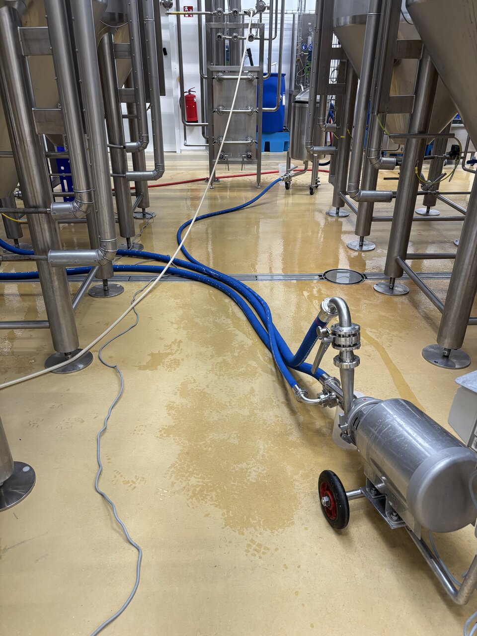
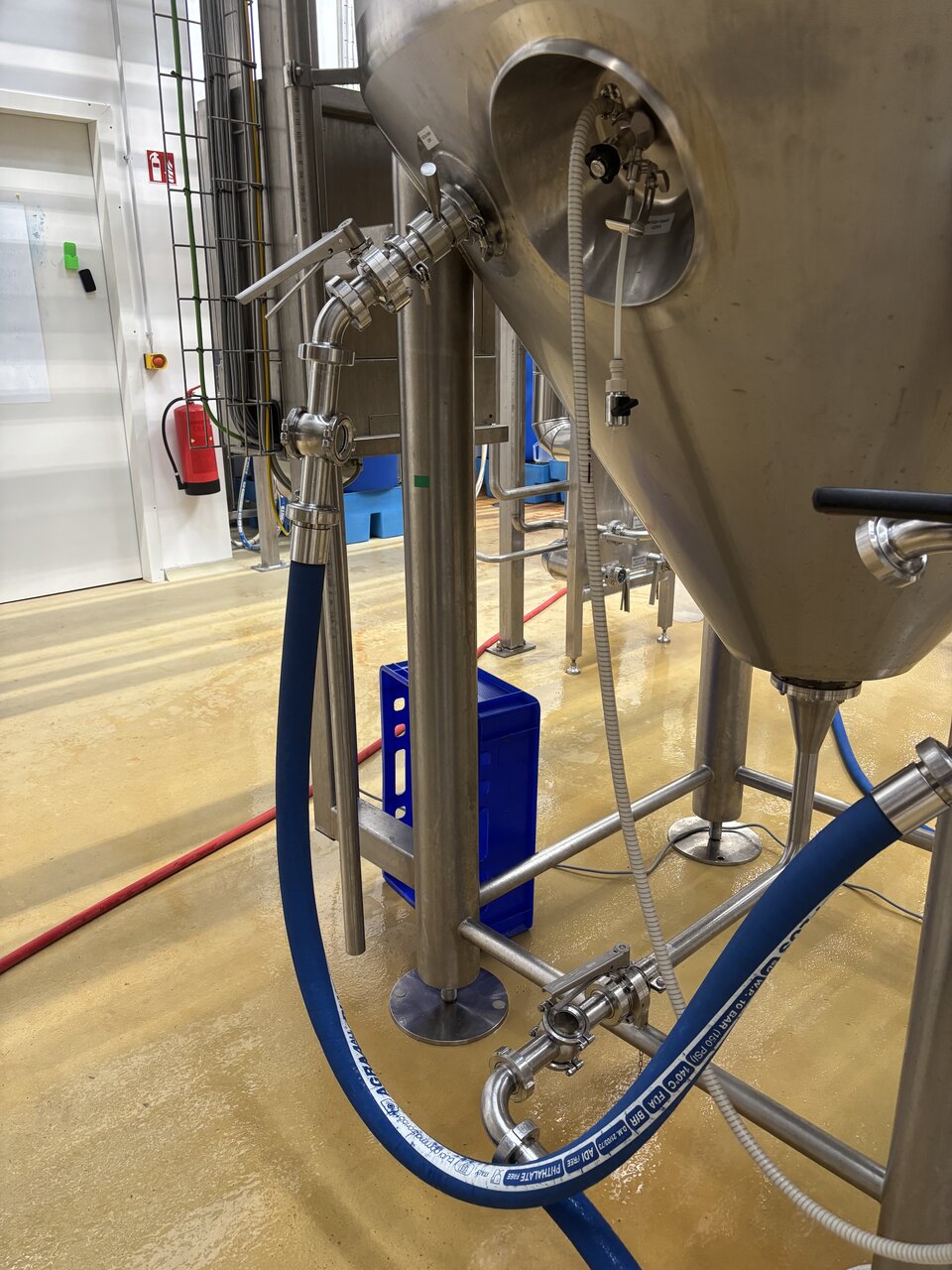
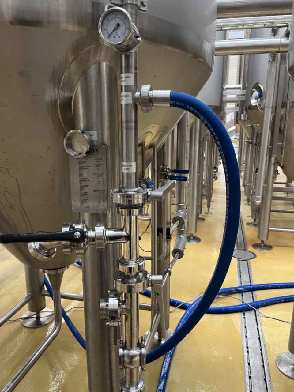
- Mobile pump (cellar pump) with T-piece on inlet and flow control butterfly valve on outlet
- Mobile dosing tank
- DN40 hoses — delivery, return, recirculation
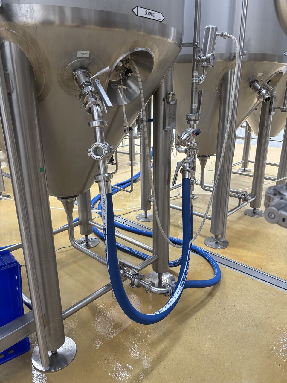
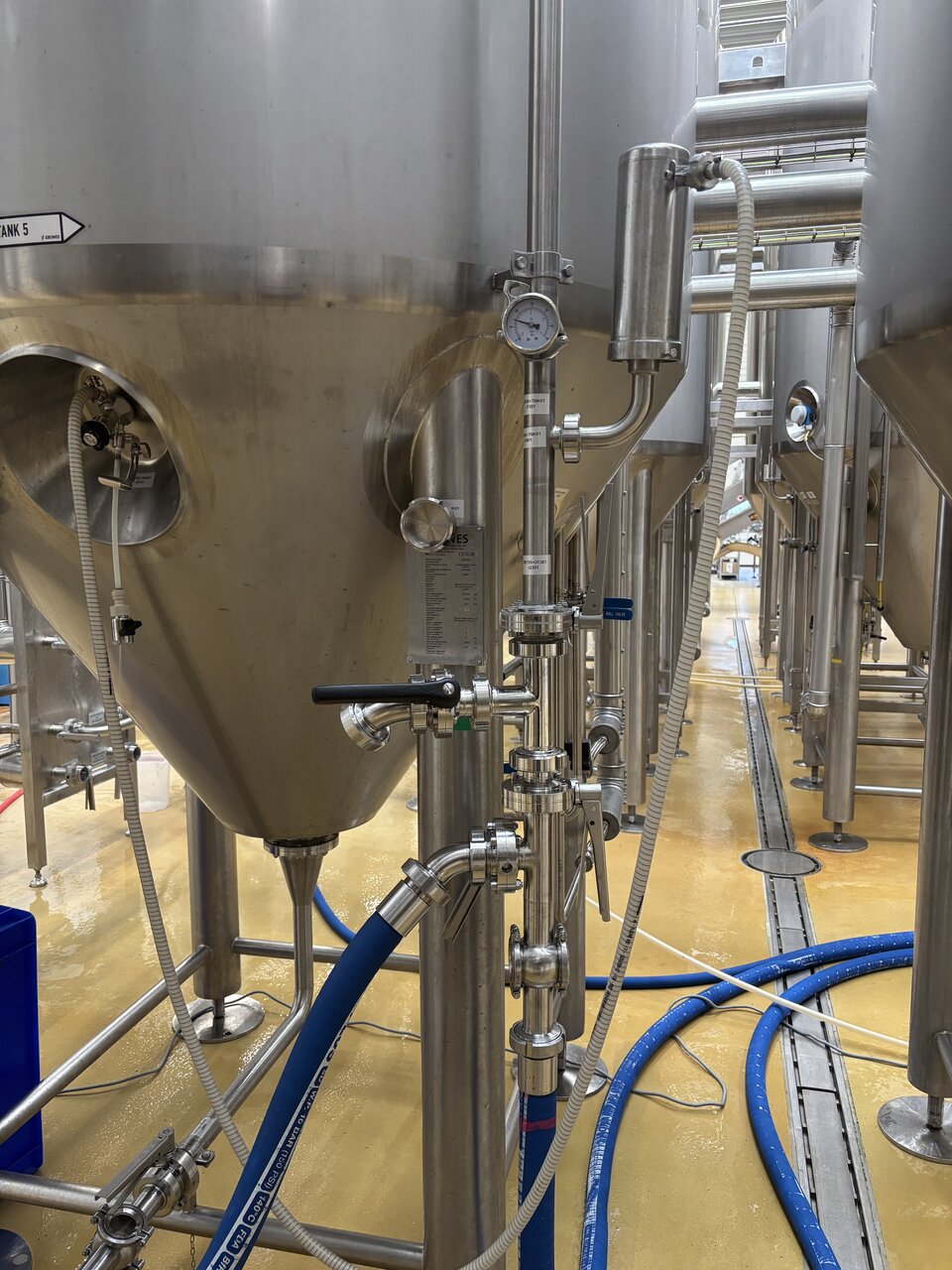
- 2 × sightglasses — one on cone outlet, one on standpipe or racking arm line
- 2 × T-pieces on CIP arm circuit:
- 1st T-piece — connects pump outlet to standpipe or racking arm line (with sightglass)
- 2nd T-piece — vent valve (with valve, 45° elbow, and cap), installed between 1st T-piece and CIP arm
- Spund Haube and piping
- Caustic (IC 1002)
- Acid (IC 3002)
- PAA (DI 1011)
- Antifoam
- Sterile air line
- Alcohol spray
- Water hose
- Bucket and red brush (for deck scrub — product contact)
- Thin red circular brush (for Zwickel on new tanks)
- ATP test device and swabs
- KRONES Celerol L7001 lubricant (for racking arm)
- Flashlight
CIP Circuit Layout
Pump outlet → DN40 hose → CIP arm T-piece → vent valve T-piece → CIP arm on tank
                               ↓
                  sightglass → standpipe or racking arm
The pump inlet T-piece has two connections: one large line from the cone (recirculation return) and one small line from the dosing tank (chemical inlet).
Chemical Dosing Reference
| Step | Chemical | Amount | Water | Temp | Time |
|---|---|---|---|---|---|
| Pre-caustic | IC 1002 + antifoam | 2.5 L + 150 ml | 2 × 80 L | 1st cold, 2nd hot | 10–15 min |
| Main caustic | IC 1002 + antifoam | 3.5 L + 150 ml | 2 × 80 L | 1st cold, 2nd hot | 20 min |
| Acid | IC 3002 | 2 L | 2 × 80 L | Cold | 20 min |
| PAA | DI 1011 | 500 ml | 2 × 80 L | Cold | 20 min |
Warning
Always send cold water first when mixing with hot. Tanks are rated to 50°C (some 55°C) — never send hot water alone. Mix cold first so the combined temperature is warm, not hot.
Process
1. Cone Dump
- Connect the gully hose from the cone outlet to the centre floor drain (middle gully). Use only the dedicated gully hose for this — do not put regular CIP lines into the floor drain. Always use the centre floor drain — the side drains near the canning line are smaller, block easily, and risk contaminating the packaging area.
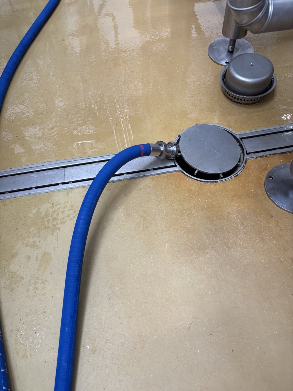
- Place a lid or cover over the hose at the cone connection to hold it down. When gas breaks through at the end of the dump the hose becomes unpredictable and can fly off.
- Open the cone valve slowly. Going too fast will pop gully covers and cause spray. Monitor through the sightglass.
- Continue dumping until the flow through the sightglass runs clear. Once gas starts breaking through, be prepared — close or manage accordingly.
If the cone is stuck or blocked:
- Connect the cone hose to the water panel. Use the booster to push water in reverse up through the cone. The booster gives approximately 2 bar on the line — without it there may not be enough pressure to clear the blockage.
Warning
Remove all tank pressure before connecting the water line. If there is pressure on both sides, water cannot move and the cone will not clear.
2. Assemble CIP Circuit
Begin assembling the CIP circuit while the cone is still draining. Connect as per the circuit layout above.
- Cone outlet → sightglass → pump inlet (large line)
- Dosing tank → DN25 hose → side inlet on pump T-piece (small line)
- Pump outlet → DN40 hose → CIP arm T-piece → vent valve T-piece → CIP arm on tank
- CIP arm T-piece side outlet → sightglass → standpipe or racking arm
3. Water Rinse
- Detach the pump inlet hose from the tank cone and connect it to the water panel.
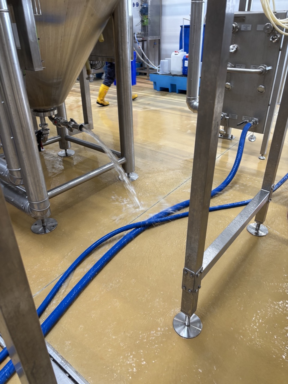
- Run the pump to push water through the CIP arm and spray ball. Water exits from the open cone outlet to the floor.
- Run until the water coming out of the cone runs completely clear. If still brown or hazy, run again briefly. Once clear, shut off — do not waste water.
- After the rinse is complete, release water from the CIP arm line using the vent valve before removing the spund.
Note
During the rinse, keep the spund set to 1.5–2 bar. If set too low, liquid will blow out uncontrolled.
4. Sterile Air Purge — 30 Minutes
- Once the CIP arm line is emptied via the vent valve, remove the spund and soak it in the caustic bath.
-
Connect the sterile air line to the spund port. A DN25 pipe is used here — connect it where the spund apparatus normally sits. Air enters at the top and pushes residual CO₂ out through the open cone valve at the bottom.
Warning
Open the sterile air valve only a tiny amount — purge very slowly. Sterile air comes from a shared generator and opening too fast can starve other equipment of pressurised air, causing failures elsewhere in the brewery.
- Purge the tank with sterile air for 30 minutes to displace residual CO₂.
During the purge — racking arm tanks (1–7):
- Remove the racking arm while purging is running. Take out all seals and O-rings. Inspect for wear and tear — replace any that are degraded.
- Hose the racking arm down thoroughly. There are hidden spots that are easy to miss.
- Soak the racking arm and all seals/O-rings in the caustic bath for 10–15 minutes.
- Reinstall the racking arm before the purge finishes. Apply a small amount of KRONES Celerol L7001 lubricant to the seals only before reinserting. Close the tri-clamp firmly but do not overtorque.
New tanks — removable Zwickel (spund port):
- Remove the Zwickel fitting using the correct tri-clamp seal — the outer diameter is the same as DN40 but the internal hole is smaller, with more rubber material to close off dead spots. Using the wrong seal leaves a dead spot inside the fitting. Brush inside with the thin red circular brush and caustic. There is always residue inside.
After purge is complete:
- Set the spund to 0 bar first. Reinstall the spund with the Spund Haube on top. The Spund Haube outlet connects to the top entry of the Zwickel — open the Zwickel. The bottom outlet of the Zwickel gets a small apparatus connected with a small valve.
- Check that the manway seal is correctly seated in the manway before closing. It can slide when the manway is moved. Double and triple check — an improperly seated seal means the tank will not hold pressure during fermentation. Check the manway seal from outside before coming down from the deck.
5. Pre-Caustic — 10–15 Minutes
Filling the tank:
- Close the cone outlet valve. Close the pump outlet valve.
- Open the T-piece valve to the dosing tank at the pump inlet.
- Fill the dosing tank with 80 L cold water. Add 2.5 L caustic (IC 1002) + 150 ml antifoam.
- Close the cold water at the panel. Open the pump outlet valve and run the pump to send the chemical mix into the tank through the CIP arm. Do not let the pump run dry — turn it off and close the pump outlet valve before the dosing tank empties.
- Switch the pump inlet hose from cold water to hot water at the panel. Refill the dosing tank with 80 L hot water (no additional chemical). Send into the tank the same way. Once all water is in, close the hot water and close the T-piece valve to the dosing tank.
Recirculation:
- Take the pump inlet hose that was connected to hot water and reconnect it to the tank cone outlet. Open the cone outlet valve. Open the pump outlet valve. Start the pump — this begins recirculation.
- Open the Zwickel drain valve slightly to get flow through it. Use the flashlight to confirm flow if needed.
- Open the valve to the racking arm or standpipe slightly — enough to confirm flow through the sightglass but not fully open. Pressure will read approximately 1.5–1.8 bar once this valve is open.
Note
When using a racking arm, lift it to approximately the 2 o'clock position. If it points downward it creates a whirlpool effect that pulls air into the cone and causes the pump to cavitate.
- Recirculate for 10–15 minutes. Open the vent valve simultaneously — this prevents the pump from pulling air from the bottom.
- Stop the pump. Reconnect the pump inlet hose to the water panel. Open the cone valve to drain. Open the vent valve simultaneously while draining.
- Once empty, close the vent valve.
6. Water Rinse — Post Pre-Caustic
- Run water through the CIP arm with the pump on. Use 4 × 10-second bursts:
- Open water, run pump for 10 seconds
- Stop pump, close delivery valve slowly (avoid pressure shocks), allow to drain fully
- Open the vent valve each time to ensure complete drainage
- Repeat for 4 cycles total
- Check conductivity at the cone outlet — target < 0.15 mS before proceeding to main caustic.
7. Main Caustic — 20 Minutes
- Fill dosing tank with 80 L cold water. Add 3.5 L caustic (IC 1002) + 150 ml antifoam.
- Send into tank via pump as in step 5. Refill with 80 L hot water and send that too.
- Reconnect pump inlet to cone outlet. Recirculate for 20 minutes at 1.5–1.8 bar with racking arm or standpipe valve open. Confirm flow through sightglass and Zwickel.
- Stop pump. Drain via cone valve with vent valve open simultaneously.
- Rinse with 4 × 10-second bursts. Check conductivity — target < 0.15 mS before going to the deck.
8. Deck Scrub and ATP
After main caustic rinse and conductivity confirmed, climb to the deck.
Before climbing: confirm the water hose is already at the deck. It is easy to forget and have to climb back down.
- Open the manway.
Note
As soon as you open the manway, inspect the tank interior. If you see a krausen line or heavy ring at the crown, scrub it now with the long red brush and caustic before doing anything else. If the ring remains after main caustic, come down, run a short additional caustic cycle (10 minutes), then return to the deck and scrub again before proceeding.
If you see a yellowish or tan layer on the cone walls or inside surface — particularly after a heavily dry-hopped beer — this is a hop protein matrix. Standard caustic may not fully remove it. It requires a targeted CIP: caustic followed by a Wasserstoffperoxid (hydrogen peroxide) cycle. Note it on the tank sheet and discuss with the team before proceeding to acid.
-
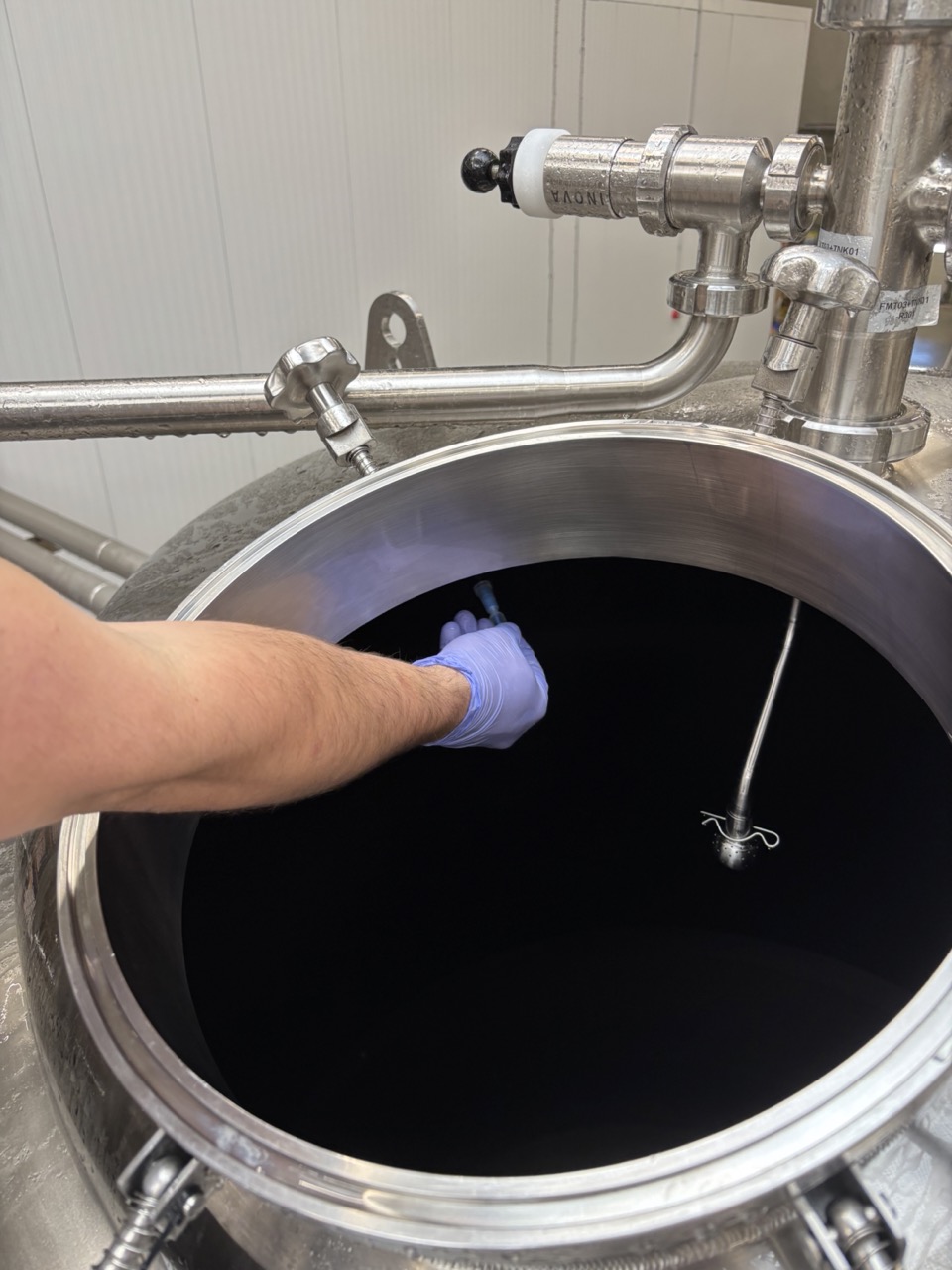
Using the flashlight, inspect the full interior: sidewalls, top of tank from inside, cone from inside, and the sprayball. If you see any dirt or residue, come down and run another caustic cycle before proceeding.
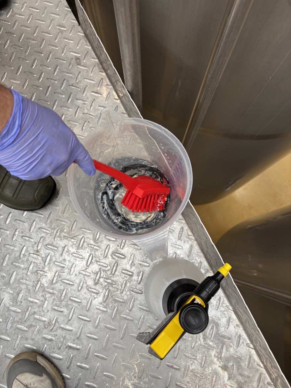
-
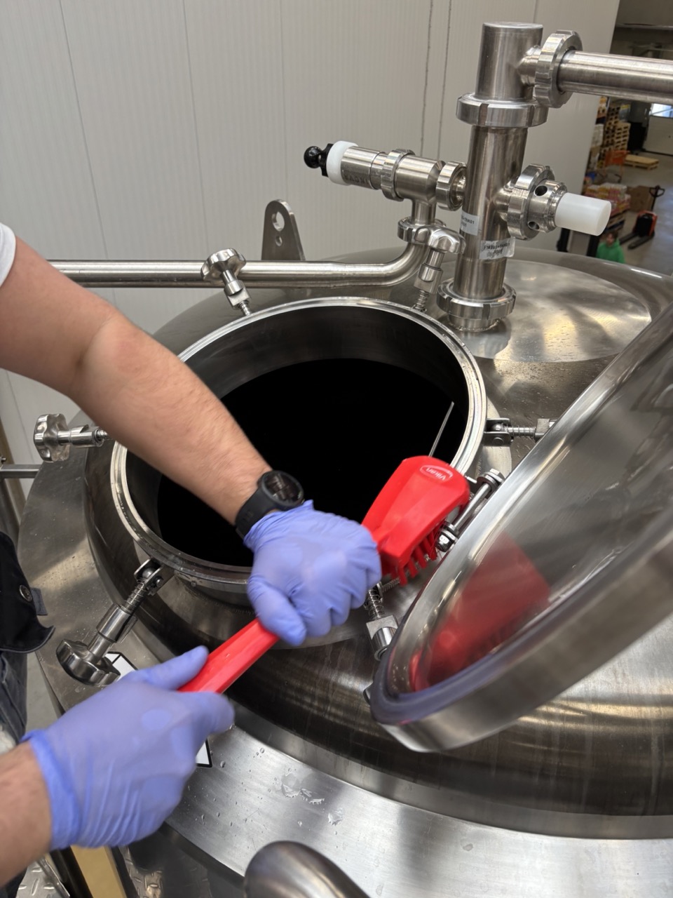
Remove the manway seal ring and place it in the caustic pitcher. You have caustic up on the deck in a pitcher for scrubbing.
-
Scrub what you can reach with the red brush: the inside of the manway, the area under the seal, and the tank wall within reach.
-
Spray down with water.
-
ATP test — swab the inside of the manway door and the tank wall within reach. Return the swab to its container before activating — do not activate until the device is ready. How to take swab samples (video reference)
- < 20 RLU → proceed to acid
- ≥ 20 RLU → come down, run another main caustic cycle (20 min), return to deck and repeat
Note
Do not ATP test if the tank fails a visual inspection — clean first, validate after. Zero is the ideal result. Up to 20 RLU is acceptable. Over 20 RLU, run another main caustic step.
- Once ATP passes, spray with alcohol.
- Reinstall the manway seal ring. Close the manway.
- Check that the manway seal is correctly seated before closing. Check from outside after closing.
9. Acid — 20 Minutes
- Fill dosing tank with 80 L cold water. Add 2 L acid (IC 3002).
- Send into tank via pump. Refill with 80 L cold water and send that too.
- Reconnect pump inlet to cone outlet. Recirculate for 20 minutes at 1.5–1.8 bar. Confirm flow through sightglass and Zwickel.
- Drain via cone valve with vent valve open simultaneously.
- Rinse with 4 × 10-second bursts. Check conductivity — target < 0.15 mS before proceeding to PAA.
10. PAA Sanitisation — 20 Minutes
- Fill dosing tank with 80 L cold water. Add 500 ml PAA (DI 1011).
- Send into tank via pump. Refill with 80 L cold water and send that too.
- Reconnect pump inlet to cone outlet. Recirculate for 20 minutes at 1.5–1.8 bar. Confirm flow through sightglass and Zwickel.
- Drain PAA via cone valve with vent valve open. Watch the cone outlet closely — as soon as it runs empty, close all valves immediately. The tank is now clean and any open valve will pull in air, mould spores, or other contamination.
Warning
Close valves as fast as possible the moment PAA is drained. You can briefly crack the cone again to remove any last residual PAA, but close it again immediately. Do not leave valves open.
There will be a small residual amount of PAA in the tank — this is acceptable. Do not rinse after PAA.
11. Breakdown and Close
- Disconnect all hoses and CIP fittings.
- Close all valves: butterfly valves, sample port, Zwickel, CIP arm, cone, vent valve.
- The tank is clean and ready to receive wort.
Note
A completed tank CIP is normally the trigger for a Wortway CIP. Set the tank status in Botec to CIP complete.
Log and Sign Off
- Record the ATP result on the printed brewing sheet and in the fermentation spreadsheet.
- Set the tank status in Botec to CIP complete.
- Add your initials to the brewing tracker — always record who cleaned the tank.
Leaving a Tank Mid-CIP (Continuing Next Day)
If the CIP cannot be completed in one session, the stopping point matters for hygiene and safety. Below is the priority ranking from best to worst, adapted to our process.
🟢 Best — Stop after acid + rinse
Sequence completed: Pre-caustic → Main caustic → Rinse → Acid → Rinse → STOP
Next day: Short rinse → PAA → use
Why this is ideal: Organic soil removed by caustic. Beer stone and mineral scale removed by acid. The surface is clean stainless with low nutrient availability — overnight microbial risk is very low. No aggressive chemistry sitting on seals. This is the preferred stopping point whenever possible.
Leave the tank: manway closed, slight positive CO₂ pressure if possible, cone fully drained.
🟡 Acceptable — Stop after main caustic + rinse
Sequence completed: Pre-caustic → Main caustic → Rinse → STOP
Next day: Acid → Rinse → PAA
When this is OK: Tank was not heavily scaled. Acid will definitely be run the next day.
Risks: A thin mineral film may form overnight. Slightly higher microbial risk than post-acid. Still generally acceptable if the tank is closed and the temperature is normal.
Leave the tank: manway closed, CIP arm cracked slightly to avoid stagnation. Label tank clearly.
🟡 Conditional — Stop after acid, before rinse (acid left in tank)
Sequence completed: Pre-caustic → Main caustic → Rinse → Acid → STOP (acid in tank)
Next day: Drain → Rinse → PAA
Pros: Very low microbial risk (acidic environment). Surfaces stay descaled.
Cons: Acid will continue acting on EPDM/silicone gaskets and valve seats overnight. Not suitable for frequent repetition — use occasionally, not as standard practice.
🔴 Not recommended — Stop after caustic (caustic left in tank)
Caustic is aggressive to seals and can cause pitting if concentration or temperature drifts. Dried caustic residue is difficult to rinse. Only acceptable in exceptional circumstances — if you must, keep it cold and diluted.
🟡 After PAA — Use within 24 hours
A tank that has been fully CIPed and PAA sanitised is ready to receive wort within 24 hours of the PAA step. This is standard practice — CIPing a tank the day before brewing is normal.
If more than 24 hours have passed since PAA, run a full CIP again before use, skipping the pre-caustic step: main caustic → rinse → acid → rinse → PAA.
Always inform the team of the tank state and expected continuation time before leaving. Label the tank clearly.
Checklist
Cone Dump
- [ ] Hose connected to centre floor drain, lid placed over hose connection at cone
- [ ] Cone dumped slowly — clear through sightglass before stopping
- [ ] Stuck cone cleared with water booster if needed — tank pressure removed first
CIP Circuit
- [ ] Assembled: cone → sightglass → pump inlet; dosing tank → pump T-piece side inlet; pump outlet → CIP arm T-piece → vent valve T-piece → CIP arm; sightglass → standpipe or racking arm
Water Rinse
- [ ] Pump inlet hose detached from cone and connected to water panel
- [ ] Water run through CIP arm and spray ball until cone outlet runs completely clear
- [ ] Spund set to 1.5–2 bar during rinse
- [ ] CIP arm line emptied via vent valve before removing spund
Sterile Air Purge — 30 Minutes
- [ ] Spund removed and soaking in caustic bath
- [ ] Sterile air connected — valve opened only a tiny amount, purging slowly
- [ ] Racking arm removed, seals inspected — tanks 1–7
- [ ] Racking arm hosed down, soaked in caustic bath 10–15 min — tanks 1–7
- [ ] Zwickel removed, correct tri-clamp seal identified, brushed with thin red brush and caustic — new tanks
- [ ] Racking arm lubricated (L7001) and reinstalled before end of purge — tanks 1–7
- [ ] Spund set to 0 bar, reinstalled with Spund Haube, Zwickel open and connected, bottom valve fitted
- [ ] Manway seal confirmed correctly seated
- [ ] Manway seal checked from outside
Pre-Caustic — 10–15 Minutes
- [ ] Cone outlet and pump outlet closed before filling
- [ ] Dosing tank T-piece opened at pump inlet
- [ ] 2.5 L caustic + 150 ml antifoam in 80 L cold water pumped into tank — pump off before tank empties
- [ ] 80 L hot water pumped in — dosing tank T-piece closed after
- [ ] Pump inlet hose reconnected to cone outlet for recirculation
- [ ] Recirculated 10–15 min at 1.5–1.8 bar — sightglass and Zwickel flow confirmed
- [ ] Racking arm at 2 o'clock — tanks 1–7
- [ ] Vent valve open during recirculation and draining
- [ ] Water rinse: 4 × 10 s bursts, conductivity < 0.15 mS
Main Caustic — 20 Minutes
- [ ] 3.5 L caustic + 150 ml antifoam in 2 × 80 L (cold then hot) sent to tank
- [ ] Recirculated 20 min at 1.5–1.8 bar — sightglass and Zwickel flow confirmed
- [ ] Drained — vent valve open simultaneously
- [ ] Water rinse: 4 × 10 s bursts, conductivity < 0.15 mS
Deck Scrub and ATP
- [ ] Water hose confirmed at deck before climbing
- [ ] Manway opened — interior inspected for krausen rings and hop protein matrix
- [ ] Flashlight inspection: sidewalls, top of tank from inside, cone from inside, sprayball — clean before proceeding
- [ ] Manway seal ring removed and soaking in caustic
- [ ] Interior scrubbed with brush and caustic
- [ ] Sprayed down with water
- [ ] ATP test — manway interior and tank wall within reach
- [ ] ATP < 20 RLU confirmed — if ≥ 20, repeat main caustic and re-test
- [ ] Alcohol spray applied
- [ ] Manway seal ring reinstalled, manway closed
- [ ] Manway seal checked from outside
Acid — 20 Minutes
- [ ] 2 L acid in 2 × 80 L cold water sent to tank
- [ ] Recirculated 20 min at 1.5–1.8 bar — sightglass and Zwickel flow confirmed
- [ ] Drained — vent valve open simultaneously
- [ ] Water rinse: 4 × 10 s bursts, conductivity < 0.15 mS
PAA — 20 Minutes
- [ ] 500 ml PAA in 2 × 80 L cold water sent to tank
- [ ] Recirculated 20 min at 1.5–1.8 bar — sightglass and Zwickel flow confirmed
- [ ] PAA drained — all valves closed immediately when empty
Breakdown and Log
- [ ] All hoses and fittings removed
- [ ] All valves closed
- [ ] ATP result logged on printed brewing sheet and fermentation spreadsheet
- [ ] Botec tank status set to CIP complete
- [ ] Initials added to brewing tracker
Troubleshooting
| Issue | Likely Cause | Action |
|---|---|---|
| Cone stuck / not flowing | Compacted trub or yeast | Connect water to cone via panel and use booster. Remove tank pressure first. |
| Pump cavitating | Air in pump inlet, or racking arm pointing down | Turn off. Bleed air from delivery side, retighten, restart. Lift racking arm to 2 o'clock. |
| Low flow during recirculation | Blocked spray ball or heavy foaming | Open manway and inspect spray ball. Clean it — do not drop fittings into tank. If heavy foam, antifoam was insufficient. |
| Conductivity above 0.15 mS after rinse | Insufficient rinse volume | Continue 10 s burst cycles until target is reached. |
| ATP ≥ 20 RLU | Residual contamination | Run another main caustic cycle (20 min). Scrub again if visible soiling. Repeat ATP. |
| Hose lifts off drain during cone dump | Gas breaking through, no lid | Stop, reposition hose, place lid over connection before continuing. |
| Tank not holding pressure after CIP | Manway seal not seated | Climb back up. Open manway carefully, reseat the seal, close and check from outside. |
| Sterile air causing brewery alarms | Air valve opened too far | Close immediately. Reopen only a tiny amount — purge must be very slow. |